背景
搞了这么个玩意儿,因为Typec的24个引脚焊盘都引出来了,为保证质量,要进行测量,从而保证其该通的通,该断的断。时间紧,没办法,看手上有F4的开发板,索性就用它来DIY了
需求
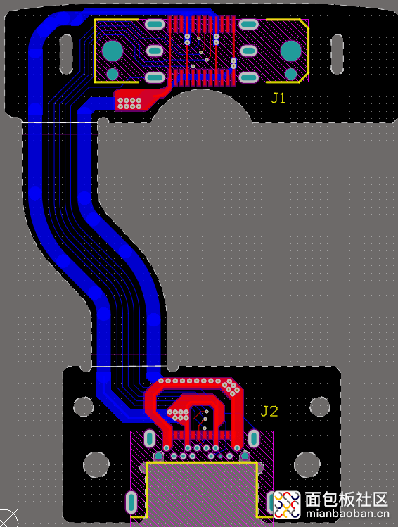
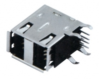
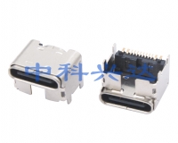
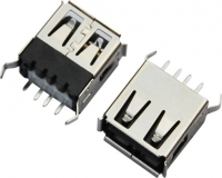
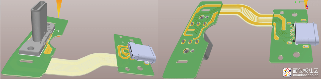
如图所示,因24个引脚中,只用了 VCC, GND, DP, DN, CC1, CC2 7个信号,外加一个外壳,所以通路只需确认这7路即可。短路就简单了,不该短的别短的就OK了。
原理
首先将公头和母座的24个脚加外壳,一共25个引脚分别引出来接到IO口上。
短路测试:将1个pin设为输出高电平,其余pin设为输入并依次读取,如果为高即为短路。因AB面短路的可能性极低,也懒的搞,所以A面只测A面,B面只测B面
通路测试:根据电路图,只测所有相连引脚,同样将1个pin设为输出高电平,其余设为输入并依次读取,如果为高即为通路
硬件制作
某宝上买了24引脚加外壳都引出来的测试板,然后焊线接到开发板的IO口上。直接上图
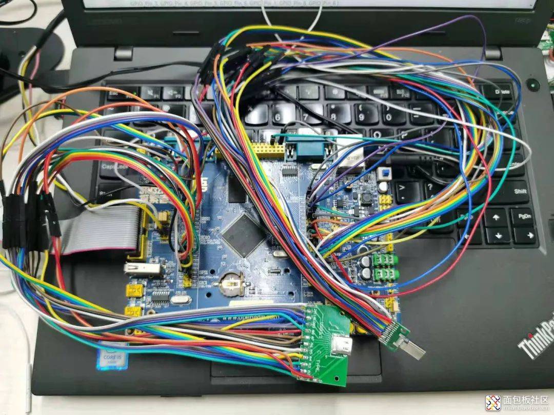
看着很乱是吧,本来线就多,还用错线了,也懒的再重新焊了,就加了下转接。
软件编程
着急用, 怎么简单就怎么来了,代码直接堆,IO口接一个填一个。
所用IO定义
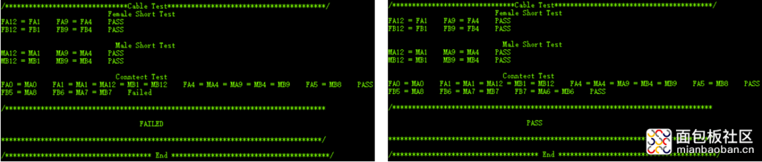
/*************************************母头A面所用IO****************************************/ uint16_t gblpFemaleAPin[13] = {GPIO_Pin_14, GPIO_Pin_15, GPIO_Pin_11, GPIO_Pin_12, GPIO_Pin_13, GPIO_Pin_2, GPIO_Pin_3, GPIO_Pin_4, GPIO_Pin_5, GPIO_Pin_6, GPIO_Pin_1, GPIO_Pin_8, GPIO_Pin_6 }; GPIO_TypeDef * gblpFemaleAPort[13] = {GPIOB, GPIOB, GPIOD, GPIOD, GPIOD, GPIOG,GPIOG, GPIOG, GPIOG, GPIOG, GPIOD, GPIOG, GPIOC}; /*************************************母头B面所用IO****************************************/ uint16_t gblpFemaleBPin[12] = {GPIO_Pin_6, GPIO_Pin_5, GPIO_Pin_4, GPIO_Pin_15, GPIO_Pin_14, GPIO_Pin_7, GPIO_Pin_15, GPIO_Pin_5, GPIO_Pin_11, GPIO_Pin_12, GPIO_Pin_13, GPIO_Pin_14 }; GPIO_TypeDef * gblpFemaleBPort[12] = {GPIOD, GPIOD, GPIOD, GPIOD, GPIOD, GPIOD,GPIOG, GPIOB, GPIOG, GPIOG, GPIOG, GPIOG}; /*************************************公头A面所用IO****************************************/ uint16_t gblpMaleAPin[13] = {GPIO_Pin_12, GPIO_Pin_13, GPIO_Pin_8, GPIO_Pin_0, GPIO_Pin_15, GPIO_Pin_10,GPIO_Pin_13, GPIO_Pin_12, GPIO_Pin_11, GPIO_Pin_1, GPIO_Pin_0, GPIO_Pin_0, GPIO_Pin_1 };GPIO_TypeDef * gblpMaleAPort[13] = {GPIOB, GPIOB, GPIOD, GPIOG, GPIOF, GPIOD,GPIOF, GPIOF, GPIOF, GPIOB, GPIOB, GPIOF, GPIOF};/*************************************公头B面所用IO****************************************/ uint16_t gblpMaleBPin[12] = {GPIO_Pin_6, GPIO_Pin_5, GPIO_Pin_4, GPIO_Pin_13, GPIO_Pin_3, GPIO_Pin_2, GPIO_Pin_1, GPIO_Pin_0, GPIO_Pin_5, GPIO_Pin_4, GPIO_Pin_6, GPIO_Pin_2 };GPIO_TypeDef * gblpMaleBPort[12] = {GPIOA, GPIOA, GPIOA, GPIOC, GPIOC, GPIOC,GPIOC, GPIOC, GPIOF, GPIOF, GPIOE, GPIOF}; /************************************通路测试所用IO****************************************/ uint16_t gblpFAConnectPin[4] = {GPIO_Pin_6, GPIO_Pin_8, GPIO_Pin_5, GPIO_Pin_4};GPIO_TypeDef * gblpFAConnectPort[4] = {GPIOC, GPIOG, GPIOG, GPIOG};uint16_t gblpFBConnectPin[3] = {GPIO_Pin_5, GPIO_Pin_15, GPIO_Pin_7};GPIO_TypeDef * gblpFBConnectPort[3] = {GPIOB, GPIOG, GPIOD}; 短路测试部分代码 aFlag++;}Delay_ms(2);} GPIO_InitStructure.GPIO_Pin = gblpFemaleAPin[i];GPIO_InitStructure.GPIO_Mode = GPIO_Mode_IN;GPIO_InitStructure.GPIO_PuPd = GPIO_PuPd_DOWN; GPIO_Init(gblpFemaleAPort[i], &GPIO_InitStructure); GPIO_WriteBit(gblpFemaleAPort[i], gblpFemaleAPin[i], Bit_RESET);} if((aFlag&0xE000) == 0xC000){printf("PASSrn");flag |= 0x01;} else{printf("Failedrn");} 通过测试部分代码 运行结果 附上原代码:MTY_TestCable_V1.rar
for(i=0; i<12; i++){GPIO_InitStructure.GPIO_Pin = gblpFemaleAPin[i];GPIO_InitStructure.GPIO_Mode = GPIO_Mode_OUT;GPIO_InitStructure.GPIO_PuPd = GPIO_PuPd_UP; GPIO_InitStructure.GPIO_OType = GPIO_OType_PP;GPIO_Init(gblpFemaleAPort[i], &GPIO_InitStructure); GPIO_WriteBit(gblpFemaleAPort[i], gblpFemaleAPin[i], Bit_SET);for(l=i+1; l<13; l++){if(GPIO_ReadInputDataBit(gblpFemaleAPort[l], gblpFemaleAPin[l])){printf("FA%d = FA%d ", 12-i,12-l);if(i==0 && l==11)aFlag |= 0x8000;else if(i==3 && l==8)aFlag |= 0x4000;elseaFlag |= 0x2000;
GPIO_InitStructure.GPIO_Pin = gblpFAConnectPin[2];GPIO_InitStructure.GPIO_Mode = GPIO_Mode_OUT;GPIO_InitStructure.GPIO_PuPd = GPIO_PuPd_UP; GPIO_InitStructure.GPIO_OType = GPIO_OType_PP;GPIO_Init(gblpFAConnectPort[2], &GPIO_InitStructure); GPIO_WriteBit(gblpFAConnectPort[2], gblpFAConnectPin[2], Bit_SET);if(GPIO_ReadInputDataBit(gblpMaleAPort[3], gblpMaleAPin[3]) && GPIO_ReadInputDataBit(gblpMaleAPort[8], gblpMaleAPin[8]) && GPIO_ReadInputDataBit(gblpMaleBPort[3], gblpMaleBPin[3]) &&GPIO_ReadInputDataBit(gblpMaleBPort[8], gblpMaleBPin[8])){printf("FA4 = MA4 = MA9 = MB4 = MB9 ");aFlag |= 0x0004;}GPIO_InitStructure.GPIO_Pin = gblpFAConnectPin[2];GPIO_InitStructure.GPIO_Mode = GPIO_Mode_IN;GPIO_InitStructure.GPIO_PuPd = GPIO_PuPd_DOWN; GPIO_Init(gblpFAConnectPort[2], &GPIO_InitStructure); GPIO_WriteBit(gblpFAConnectPort[2], gblpFAConnectPin[2], Bit_RESET);